1. Introduction
NMAP is a well-known tool [4]. It enables, among other things, a client machine to fingerprint a remote one. We want to do the same thing for the devices on the path between two machines communicating together. In theory, this is useless because the devices on the route should never interfere with the application-layer connection. This is the well-known end-to-end principle proposed in the 1960s by Baran [5] and Davies et al. [6] and subsequently implemented in the TCP/IP architecture. The paper by Saltzer et al. [7] precisely articulates the arguments in favour of such a design for distributed systems.
These principles are certainly still valid. A TCP connection is, indeed, an end-to-end connection. However, the end of the connection is not always where the user expects it to be. For instance, imagine a user whose browser is configured to use a web proxy. When the user visits a web site, their view of the world tells them that they are connected to that web site. In reality, the TCP connection initiated by the browser ends at the machine where the proxy server resides. This is, of course, a trivial example. In today’s networks, there are many other such instances where a device on a path between two communicating endpoints could interfere with their communication. Such interference can take various forms and take place at various layers. It can be as drastic as changing theTCP endpoint, such as in the case of the web proxy, but it can be more subtle, such as changing the source or destination IP (in the case of a NAT device) or delaying packets (in the case of a traffic shaper). As in [3], we collectively refer to all such devices as semi-active components.
Semi-active components aim at being beneficial for the end user. For instance, they can improve security (firewall, WAF, IPS, etc.) or performance (CDN, web proxy, etc.); they can also provide better access to the network (traffic shaper). Unfortunately, like the proverbial double-edged sword, their mere existence can also be detrimental to security. If compromised or misconfigured, the capabilities of such devices could be misused by attackers to their advantage. The same holds true if an intruder manages to insert their own semi-active component into a route between two devices.
One would hope that cryptography could come to our rescue to ensure true end-to-end connectivity. This is indeed the expected benefit when usingTLS [8] (or IPSEC [9]) at the transport layer (or network layer). Once more, the devil lies in the details. The reality is that it is almost impossible for end users to be sure that, under the hood of the various layers, their connection is truly an end-to-end one. For instance, in many companies, a Web Access Firewall (WAF) will intercept, decrypt and re-encrypt TLS connections to protect end users, effectively deceiving them. From a networking point of view, there is almost no difference between a genuine WAF, installed by the right authorities, and a malicious device, inserted by an attacker, carrying a so-called man-in-the-middle attack, as described later.
As we can see, semi-active components matter. It is very important to verify that the legitimate ones behave the way they should, i.e. are not compromised or misconfigured. It is also very important, perhaps even more so, to detect the presence and identity of any other semi-active component in the routes we use. The framework we propose in this paper answers the following two research questions:How to detect and identify semi-active components between two endpoints?How to verify that a known semi-active component is behaving the way it should?
To answer these questions, the paper is structured as follows. Section 2 positions our work with respect to state-of-the-art practices. Section 3 presents the architecture of our new platform. It starts by introducing some terminology (3.1), then clearly states its specifications (3.2), discusses its design choices (3.3) and ends with a description of its implementation (3.4). Section 4 proposes two simple use cases in order to exemplify the usefulness of the platform, its simplicity and modularity. Section 5 concludes the paper by mentioning a number of different use cases and by inviting readers to contribute to this collaborative platform, either by deploying one of its elements in their own networks or by contributing to one of its modules.
2. State-of-the-art Practices
Semi-active components have mostly been looked at in the literature through the prism of man-in-the-middle (MITM) attacks, in which an intruder intercepts a connection and impersonates one of the two communicating parties. Many variants of these attacks exist but the most frequently mentioned do take advantage of weaknesses in the ARP or theDNS protocols, as explained in [10]. Solutions have been proposed to detect these attacks. They are usually quite specific, focusing on the symptoms of a single type of threat. For instance, in [11] the authors propose relying on the delay introduced by the attacker during the processing of packets. This method, although intuitively correct, has a significant drawback. It requires knowing the ground truth value for each connection and thus it cannot easily be generalised to connections taking place on the Internet. In [12] the authors propose the use of a neural network to study the response behaviour and classify the connection. The authors of [13] note that deep-learning-based approaches are not robust to perturbations and that knowledgeable attackers may use adversarial attacks to bypass such detection. Finally, Trabelsi et al. propose a solution for detecting MITM attacks in the context of local area networks (LANs) [14]. Their approach is interesting in the sense that it also detects threatening devices by running some active tests. They do so in order to detect those who act as routers. It does rely on ARP cache poisoning though, which is possible in their target networking environment, LANs, but impractical on the general Internet.
In [15] the authors present a detection system that identifies web proxies. Their system records and analyses incoming packets to match them with well-known proxy patterns. To read the content of the encrypted payload and identify the patterns in the data, their method uses SSL stripping [16] to disable TLS. This method assumes that we can downgrade a connection from HTTPS to HTTP and is thus impractical. Moreover, it also creates a security gap as all the traffic between their detection system and the end-user is now in clear text. Chiapponi et al. present in [17] a detection method aimed at bots using proxies to scrape web sites. This method is based on the roundtrip time difference for the packets sent from the server to the proxy and those sent to the bot itself (through a TLS tunnel). A large measurement campaign validates this idea experimentally, and the data are then used in [18] by Champion et al. to find a method capable of geolocating the machines involved.
Our new contribution has mostly been inspired by two other pieces of work: Netalyzr, by Kreibich et al., published a dozen of years ago [1, 2], and the more recent work by Vitale et al. [3] on Inmap-t.
As far as we can tell, Netalyzr [1] represents the seminal work in the detection of semi-active components. It is based on a client-server architecture. A user connects to the server and downloads a Java program which runs within their browser. This program executes a series of tests against the connection, with the server aiming at detecting the presence of semi-active components between the client and the server. For instance, in [2] the authors use it to discover the presence of a proxy server between a client and their server. In their tests, they were sending well-crafted packets to trigger some side effects induced by semi-active components. Since both the server and the Java program are synchronised, they know what is supposed to be sent at any point in time. By comparing what they receive with what they expect to receive, they can infer the presence of some semi-active components. For example, in one test of [2], the server replies to the initial SYN packet of the establishment of a 3-way TCP handshake, by a TCP RST packet as opposed to the expected SYN-ACK one. If no proxy exists between the client and the server, the Java program will indeed receive the sent RST packet. If a proxy exists, its kernel will, in most cases, complete the 3-way TCP handshake with the client before receiving the RST packet from the server. The Java program infers the existence of a proxy as soon as it receives the unexpected SYN-ACK packet. This solution has been available as a free service for several years but has unfortunately been discontinued since 2019. Maintenance costs of the service and the issues associated with the Java language are the reason for its demise [19]. Although Netalyzr represented a laudable first attempt at detecting semi-active components, it was only capable of detecting them on paths that were leading to the targeted test server. A knowledgeable attacker would therefore have had little difficulty in circumventing the detection provided by this solution.
Inmap-t, proposed in 2021 [3], aimed at l everaging the Testing and Test Control Notation Version 3 standard (TTCN-3) [20] to test the security impact of intra-network elements. TTCN-3 is a standard maintained by ETSI that offers a modular testing language and an independent e xecution environment. Its usage is normally reserved for testing the quality and conformance of a given implementation of a client or ser ver for a specific protocol. In their work, the authors instead leverage the environment to test the network connection taking place between two machines, namely, to detect the presence of semi-active components such as an Intrusion Prevention System (IPS) [21] or a firewall. As opposed to Netalyzr, the authors now offer a fully distributed environment populated with numerous devices that can communicate together and test a number of different paths. The results, while promising, also reveal the drawbacks associated with the choice of TTCN-3 as an underlying platform. According to the authors, the learning curve to use this environment is very steep and the heavily C++-inspired notation of the configuration files does not help in that regard. Furthermore, TTCN-3 comes with its own execution environment whose installation is quite heavy and cumbersome. Last but not least, the software architecture design imposes the constraint of grouping all possible tests into a single binary. The net result is that every new test increases the overall size of the code to be pushed on all participating machines. Every modification to an existing test requires pushing a whole new version of all tests to all machines.
Netalyzr and Inmap-t have shown the value and the feasibility of detecting semi-active components. They also have limitations that hold back their wide adoption for carrying out these tests systematically. In this work, we leverage the lessons learned from these previous attempts and come up with an architectural design, which not only addresses their shortcomings but also greatly increases the diversity of tests that we are able to run.
3. Architecture
3.1 Terminology
Our work leverages the key concepts developed in [3], but greatly simplifies the architecture and, more importantly, enriches its capabilities with novel contributions.
In [3] the authors had to introduce the TTCN-3 terminology for their system to be understandable. It included several well-defined terms, such as Main Test Component (MTC), Parallel Test Component (PTC), Test System Interface (TSI), Port, Module and Verdict Although we are not using any of these notions, we retain two key ideas: i) test case and ii) test campaign, and we redefine them as follows:
Test case: A test case is a small program running in a synchronized way on two (or more) machines to test a specific property of an element in a given route. It defines the details of the sequence of packets to be sent, as well as the information exchanged between the machines while running the test case. It is typically defined by a finite state machine.
Test campaign: A test campaign is a larger program running in a synchronized way on two (or more) machines to characterize one or more elements in a given route. It can be seen as a sequence of test cases or of other test campaigns. It is typically defined by a decision tree whose main components are test cases or test campaigns.
Primitive: A primitive is a simple function that we define. Its implementation remains hidden from the user and usually involves some Python and Scapy [22] code. Test cases can only be made up of primitives. This enables us to completely separate the definition of a test case from its implementation. The creator of a test case is not going to be exposed to Python code. Moreover, if we decide to change from a Python implementation to a C++ one, for instance, the test cases and test campaigns would remain untouched.
3.2 Specifications
In this section we describe the high-level specifications of what we aim to achieve in using our new solution. The next subsections will cover our design and implementation choices (subsections 3.3 and 3.4).
At the highest level, what we want to do is to build a system that enables us to answer the two research questions defined in section 1, namely:
How to detect and identify semi-active components between two endpoints?How to verify that a known semi-active component is behaving the way it should?
Building upon the lessons, drawbacks and weaknesses from previous work [1, 3], we want our solution to satisfy the following five properties:
Ease of useEase of deploymentModularityScalabilityFlexibility
We now briefly elaborate on each of these properties.
Ease of use: We target end users who do not have any particular networking or security knowledge. The solution must hide all its low-level complexities and provide a simple interface for them, such as verifying whether or not a WAF monitors their connection to the Internet.
Ease of deployment: Our platform aims at being a large, open and collaborative distributed system. The more people deploy our solution at their site, the richer the system becomes. This precludes a complicated time-consuming system setup, such as the one required by a TTCN-3 based solution.
Modularity: The creation of a new test campaign comes down to combining previously defined test cases and/or test campaigns. The same holds true for test cases that can take advantage of previously defined finite state machines by “calling” them in. Our software environment must facilitate such code reuse of test cases and campaigns by defining them as well-defined modules, with precisely specified input and output.
Scalability: As opposed to the solution described in [3], the definition o f a new test case should not increase the code size of all existing test campaigns. Also, the cost and complexity for distant machines to run a given test campaign should be independent of the number of machines participating on our platform and running other test campaigns independently on their own.
Flexibility: As opposed to the solution described in [1], we do not wish to limit our analysis to the routes that lead to a single server providing the Java code. We also want to avoid being confined to the sole routes connecting the machines participating on the platform, as in [3]. We want to be able to test the properties of the route between any of the end user machines and any server on the Internet.
In the next subsection, we outline the design choices we have made to build an open platform that would satisfy these properties.
3.3 Design
What we are trying to achieve can be summarized as follows: Some remote parties decide to test the properties of a specific route on the Internet.They agree on what data to send: where, when and how. This is defined in the test campaign that they all agree to run.To evaluate a given property, they compare the packets they receive to the ones they expect to receive, as per the definition of the test campaign.They adjudicate on the results of the tests.
To justify our design choices, we present them according to three major components of the platform we have built, namely:
Overall architectureData and Control communication channelsTest cases and test campaigns
Architecture: Our architecture consists of three types of machines: worker,proxy and master. A worker is a machine that runs a test campaign – either the client machine that wants to perform a test on its connection path to another endpoint or a trusted machine registered in the network. A proxy node, on the other hand, does not perform any test. It should be accessible to the remote workers so that they can communicate together when, for instance, they are unreachable from the Internet because of a firewall.
The master node role puts the workers (and the proxy when necessary) in touch and shares with them the test campaign they have to run. Once this is done, the workers do not use the master node anymore1.
Test cases and test campaigns: Test cases are defined thanks to a graphical user interface using a finite state machine formalism. They indicate by means of well-defined primitives what packet should be sent by whom to where, what to do when receiving a packet, what field to check, etc. These finite state machines can then be combined into test campaigns, under the form of decision trees. Test campaigns are stored within the master node and pushed to workers when they need to be run. All workers receive the same test campaign and interpret it according to the role each has to perform. To synchronise their execution, the workers do exchange control messages using the channels described hereafter.
Data and control communication channels: We use two channels to enable the workers to execute a test campaign: i) a data channel and ii) a control channel. The data channel is used to send packets on the route we want to test. The control channel, as its name implies, is used to exchange control messages between the workers to synchronise the execution of the tests. It is worth noting that the data channel does not necessarily follow the same route as the control channel.
At this stage, it is probably worth providing a simplified high-level example of what our solution aims at doing and how this can be achieved.
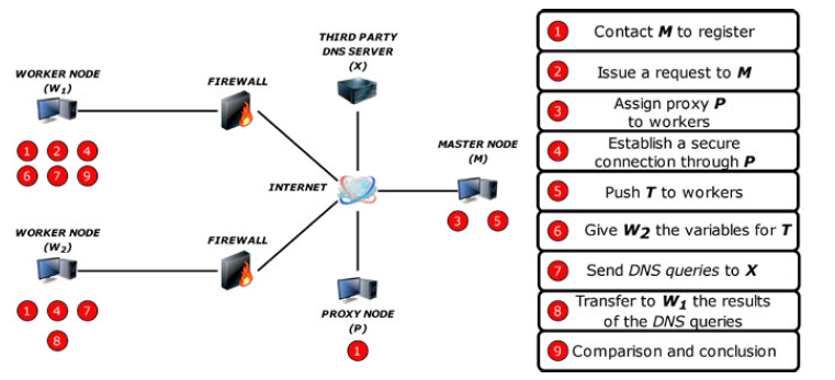
Let us imagine that we have two workers W1 and W2, a proxy P, a master node M and a DNS server D. W1 wants to know whether its DNS requests to D are intercepted by a third party and redirected to another DNS server that would provide a different IP for a given request R than the one D would return. This is one of the classical ways to redirect web request to a WAF without having to touch the user’s machine configuration. Let us further assume that both W1 and W2 are located behind firewalls and cannot be contacted directly by one another. This situation is represented in Fig. 1.
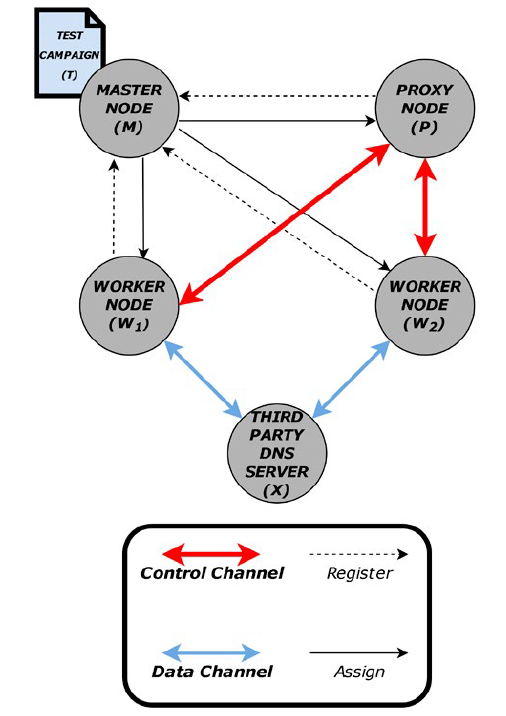
To run this test, the following steps must be performed:
W1, W2 and P register with M and maintain a secure connection to it.W1 issues a request to M to run the test campaign T with W2.M assigns P to act as a proxy for the control channel between W1 and W2.Both W1 and W2 establish an IPSEC tunnel to P and use them to establish a trustworthy end-to-end TLS connection between W1 and W2, passing through P. In the latter, we will refer to that secure end-to-end connection as the control channel.M uses the existing secure connections to push T to W1 and W2.W1 and W2 send R to D.W2 sends the result of the DNS answers to W1 through the control channel.W1 compares what it received fromW2 with its own DNS replies and reaches a conclusion for the test accordingly2.
This very simple example highlights a couple of important elements. First, the route to test is not necessarily between the nodes we own. Second, the control channel is not necessarily a direct connection between two workers, it can go through a proxy when needed. Third, the campaigns are uploaded on a case-by-case by the master node to the workers. Fourth, the campaigns are functions whose input parameters are instantiated by the workers and agreed upon via the control channel.
The next subsection gives more details on the way this platform has been implemented.
3.4 Implementation
The previous subsection presented the design of our solution based on three elements: the tests, the communication channels and the architecture. In the following subsection, we describe the implementation of each of these.
Test case: We represent a test case using finite state machines. The four main components that constitute these state machines are the following: StateTransitionActionNesting feature
To present each of these components we use the simple example presented in Fig. 2. We present two simple, yet genuine, use cases in section 4.
State: A state is represented by a light grey box with a blue header in Fig. 2. It is defined as a sequence of actions. Every finite state machine starts with an initial state that triggers an event STARTED at the beginning. A state possesses its own local variables. To transition from one state to another, we need to trigger an event whose name matches a transition that links these two states.
Transition: A transition is represented by a light grey box with a dark grey header (Fig. 2). It represents a direct path from one state to another. To leave the current state, an event with the same name as a transition linked to that state must be triggered. Depending on its implementation, the execution of a primitive can directly generate events responsible for this change of state. This is, for example, the case when we call the DONE primitive to trigger the DONE event. Events can also be generated by external elements, such as the reception of a packet or a timeout. A transition may use guards to specify the conditions on the local parameters of the current state.
Action: We refer to a command that a state can execute as a state action. It can fall into two categories, depending on the moment we want the program to execute it: An Entry action executes a primitive as soon as we enter a new state.An Exit action executes a primitive when one of the possible events to leave the current state has been caught (but after having executed all the Entry actions).
Since states possess their own set of local variables, we define a transition action as the special action that uses the SET primitive to assign the value from one state local variable to another state local variable.
Nesting feature: To create modular, understandable and easy to modify test cases, we implement something referred to as the nesting feature. This mechanism enables us to call nested finite state machines. We carry out this operation with the CALL primitive in the parent. Then we use the GET_PARAMETERS primitive to retrieve the input arguments in the nested state machine. The number of parameters associated with this primitive must match the number of parameters when the parent uses CALL (without the name of the state machine called). This is shown in Fig. 2, where the MAIN state machine calls the DOUBLE one.
Figure 2. Representation of our implementation of two finite state machines. The first one (top) is responsible for selecting a random value between 1 and 2. If the number is 2, it doubles this value by calling the second one (bottom). At the end, the main finite state machine prints the result and returns it back.
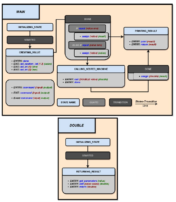
Similarly, the number of output parameters of the CALL primitive must match the number of parameters provided by the RETURN primitive. The idea behind this is to create a higher level of abstraction that is similar to traditional programming libraries. We take advantage of other finite state machines already written, so that we can reuse them across different test cases.
The transformation from a state machine representation to executable code is a key functionality that our solution implements. We use Xstate [23] as it provides a complete set of features to easily manage state machines, such as adding states, actions or transitions. Its main advantage is that we can export the representation of the state machine into JSON format afterwards. Our Python program then parses this JSON to automatically obtain the program to run for the test case.
Test campaign: As we mentioned earlier, test campaigns are composed of test cases. When test cases end, they can output different values using the RETURN primitive followed by the returned values. We use decision trees to aggregate their results and define test campaigns. Let us imagine that we want to do a test campaign that runs the MAIN test case two times consecutively and we want to know the sum of both results. The test case can only return 1 or 4. The decision tree representing the test campaign is shown in Fig. 3. We start from the root and each node represents a test case where its return value gives us the next node in the path. The test campaign finishes when it reaches a leaf node. The possible results are thus 2, 5 or 8.
Figure 3. A decision tree that repeats sequential test cases until it reaches a leaf node where it outputs its result.
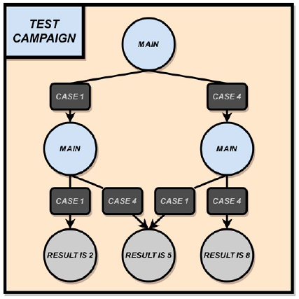
In that case the example is trivial, yet it shows how to combine test cases into a test campaign to answer questions that are more complex. We can reuse unitary tests for different test campaigns. This hides the complexity from the user and it provides us with a modular solution.
Data channel: The data channel enables us to send (or receive) packets to remote machines that we do not necessarily control through the SEND (or WAIT_PACKET_SIGNAL) primitives. We emit, filter and sniff packets using the Scapy library in Python. Each transmission of a packet triggers a PACKET_SENT event. Received packets that passed the filter phase are stored in a FIFO data channel queue to ensure that no packets are lost. When the program executes the WAIT_PACKET_SIGNAL primitive, it checks whether packets are available inside the queue whose name was given as argument. If this is the case, a PACKET_ AVAILABLE event is generated and the oldest packet in the queue is processed. Otherwise, after a certain time has elapsed, it raises a TIMEOUT event.
Control channel: We specify the behaviour of the control channel in the definition of the state machine to synchronise the workers. This comes with its dedicated set of primitives and events to maintain the correct flow of the state machines.
The primitive WAIT_READY_SIGNAL triggers the event READY when the node successfully creates a control channel.The primitive WAIT_SYNC_SIGNAL triggers the event SYNC_ AVAILABLE when the node has an available sync message in the control channel queue.The primitive SYNC triggers the event SYNC_SENT when the node sends a sync message.
We define a sync message as a message whose reception acts as a checkpoint. It is responsible for the synchronisation of the worker nodes. A sync message can embed data to provide a remote node with some information securely using the control channel. We use the same queuing mechanism as the data channel to listen constantly for sync messages. This guarantees that no packet is lost due to concurrency issues between worker nodes. We call it a control channel queue and it is unique for each control channel created between two nodes. Section 4 provides two use cases to show how our framework takes advantage of it. Finally, to ensure that we can start sending packets through the control link, we use the WAIT_ READY_SIGNAL primitive. As soon as the channel is ready, it triggers the event READY to resume the execution of the test case. In order to protect our control channel, we use TLS and IPSEC where necessary. Our solution uses TLS with mutual authentication to link two remote worker nodes. We encapsulate TLS using IPSEC to create a tunnel that connects the worker nodes and a proxy when they are hidden behind firewalls. It enables the workers to redirect the traffic so that they can initialise the control channel. To ensure that all nodes perform proper mutual authentication, we designate a master node as the only trusted authority. This is the sole node able to sign the certificates associated with the different public keys announced by the other nodes. This architecture enables us to revoke the certificates of compromised machines using the OCSP [24] protocol.
Architecture: In order to assign the test campaigns to the different nodes of the network, we use Ansible [25]. Its use only requires Python and SSH, which are often installed by default on Linux machines. The description of that part resides outside the scope of this paper.
In the following Section, we provide two simple use cases, one for UDP traffic and the other for TCP connections, to exemplify how these concepts can be put into action from a practical point of view.
4. Use cases
4.1 DNS redirection
Our first use case is the one eluded to in subsection 3.3 in which a client tries to determine if their DNS server returns different results than the ones other users are seeing for the same domain name. There are many reasons why network administrators routinely do this. To render things concrete, we can think of a network that uses a Web Access Firewall to check any outgoing HTTP request in order to detect those coming from possibly compromised machines trying to “call home”, or to block requests sent to sites forbidden by the local security policy. This is a very common practice in enterprise networks. To force the traffic to go through the WAF, several techniques exist, such as using DNAT or WPAD. Another simple technique consists of using DNS. Whenever a client uses DNS to resolve the name of a web server it wants to access to, the returned IP is that of the WAF instead of the actual machine. The client initiates the connection to the IP of the WAF, which decides whether the request is to be blocked or not. If the traffic is allowed to go through, the “Host:” HTTP header enables the WAF to forward the traffic to the right destination. There is a problem if the initial DNS request was not made to generate some HTTP traffic afterwards. If this is indeed the case, this approach prevents the establishment of the connection, since the WAF does not find in the application payload the identity of the server to contact on behalf of the client. Consequently, using this technique requires using heuristics at the DNS server level to decide whether or not to RETURN the real IP or the IP of the WAF to avoid blocking non-HTTP traffic. Domain names starting with “www.” will typically be resolved by the WAF IP, whereas names starting with “ftp.” or “smtp.” will not, for instance.
In our use case, a client wants to determine whether or not their network applies such DNS-based protection and, if so, which heuristics are being used at the DNS server level.
Setup: We have a client W1 who wants to detect if DNS requests sent to D are redirected using another remote machine W2. Both workers W1 and W2 have registered their availability to the master node M and maintain a secure connection to it. Upon W1’s request, M notifies W2 that W1 wants to run a test campaign with it. If W2 agrees, M, which knows that both are sitting behind a firewall, assigns a proxy P and provides the test campaign T along with its parameters to all the parties. W1 and W2 establish an IPSEC tunnel to P and then a TLS connection between them through P. They finally instantiate two separate data channels with D. We use Fig. 4 to illustrate our architecture. The client can then repeat this process with different requests to identify the heuristics used, if any, or with other WK workers to double check its results.
Test case: We present here how this use case can be modelled as a finite state machine. As mentioned in subsection 3.4, we rely on the Xstate graphical interface [23] to create the state machines and to automatically generate a JSON file that contains all their semantics. That file is then sent to both workers, parsed, and interpreted by a generic piece of code capable of executing any such state machine. It is worth noting that, even though both workers execute different tasks, they both interpret the same file. We have made this design choice to avoid having numerous files associated with a given use case that could, if modified independently, become out of sync. Having only one file per use case for all workers eliminates this risk.
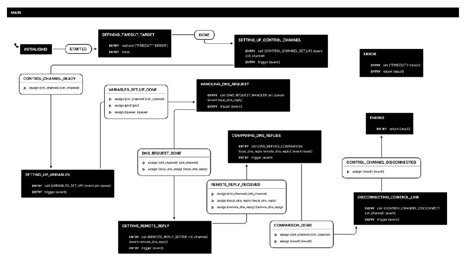
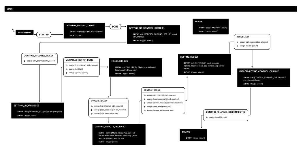
Main finite state machine: This test case can be represented by only 7 states, which are represented in Fig. 5. It is thus easy to read and understand what this use case represents. The simplicity is obtained thanks to the modularity of the design. Indeed, each state in this finite state machine corresponds to a full finite state machine that remains hidden at this level of abstraction. We will briefly list the various states and their functions. We discuss each state in more details afterwards.
DEFINING_TIMEOUT_TARGET: a catch all state to handle all timeout events in a generic way.
CONTROL_CHANNEL_SET_UP: builds the control channel.
VARIABLES_SET_UP: builds the DNS packet according to the input provided by W1 to M and returns the name of the data channel queue on which the received packets are stored.
DNS_REQUEST: sends the DNS request and waits for the reply.
REMOTE_REPLY_GETTER: exchanges the DNS replies between the worker nodes.
DNS_REPLIES_COMPARISON: compares the DNS replies.
CONTROL_CHANNEL_DISCONNECT: closes the control channel. In what follows, we will briefly describe all the state machines required to run this use case, starting from the main one at the highest level of abstraction, and following by the ones that are invoked from within this main one.
MAIN: This state machine is the main component of our test case. Its execution is triggered by M. It runs on W1 and W2. Like every state machine, its initial state is named as INITIALISING. Launching the execution of the finite state machine (or invoking a finite state machine, in the case of a nested feature) generates the event STARTED which triggers the first transition of the state machine. In this state machine, all subsequent states will invoke the CALL primitive to execute another state machine. The end of the state machine is characterised by a state named ENDING, which invokes the RETURN primitive with a list of arguments that represent the results of the execution of the state machine.
DEFINING_TIMEOUT_TARGET: This first state is very specific. It only invokes the primitive REDIRECT before generating the DONE event to move to the next state. The primitive REDIRECT associates an event with a specific state. In this case, we associate the TIMEOUT event with the ERROR state. This means that, no matter where we are in the finite state machine, if the TIMEOUT event is raised then the next state of the state machine will be the ERROR state. This is a convenient and simple error handling mechanism.
CONTROL_CHANNEL_SET_UP: This state uses the CALL primitive to invoke another state machine, the role of which is to create the control channel between W1 and W2. Whether this control channel goes through a proxy or not is irrelevant for the use case and remains hidden to the creator (or user) of the state machine. The usage of a proxy will be required if both are hidden behind a firewall. If only one is unreachable, that one will be the one initiating the connection to the other one. If both are reachable, M decides which one initiates the connection.
Generally speaking, it is M that, together with the test campaign, informs the workers (and the proxy when needed) as to whether they have to initiate a connection (and to whom), or whether they have to be ready to accept a connection (and from whom). When the invoked state machine has terminated, the TRIGGER primitive is invoked. As its name implies, it triggers an event in order to move to the next state. The specific event triggered is the output of the called state machine. In this case, there is only one possibility, CONTROL_LINK_READY, but in the general case there could be several results leading to different states.
VARIABLES_SET_UP: This state is responsible for creating the same DNS request R on W1 and W2. All the low-level complexity is hidden behind the nested state machine. It will, for instance, create a UDP packet with destination port 53 corresponding to the DNS protocol while the source port is set as random. It also specifies the destination IP address and the requested domain name, as specified by W1 to M. In addition to the packet, the state machine defines a filter on the source port of the packet for the sniffer, so that the workers only listen to the DNS replies sent by D for the request R. The nested state machine links this filter to a data channel queue before starting to listen and push packets inside it. At the end, the state forwards the name of the queue and the crafted packet to the next state.
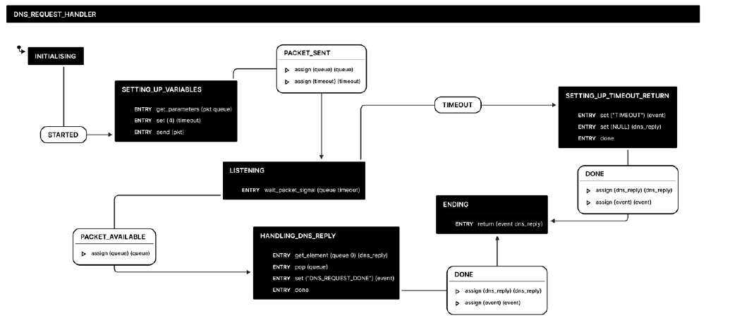
DNS_REQUEST: This state calls a nested state machine responsible for the emission of the crafted packets and the reception of the DNS replies on both W1 and W2. Its representation is shown in Fig. 6. The two worker nodes send the DNS queries to D using the SEND primitive. They process the DNS replies stored on the data channel queue using its name and the WAIT_PACKET_SIGNAL primitive. The state then forwards the DNS replies received to the next state to compare if they are the same on both workers.
REMOTE_REPLY_GETTER: Before disconnecting the control channel, we need to ensure that the DNS replies received by W1 and W2 are the same. We use the sync mechanism presented in subsection 3.4 to fully synchronise our state machines. The following steps show how it works in that specific case.
A worker node uses the SYNC primitive to send the payload of the DNS reply received within a sync message to the other worker.It switches to a new state using the SYNC_SENT event that is triggered and waits for an available sync message from the other node using the WAIT_SYNC_SIGNAL primitive.When a sync message is available on the control channel queue, the state machine triggers a SYNC_AVAILABLE event to leave the current state. The node finally extracts and stores the payload inside a variable. That variable is returned to the main state machine.
If an error occurs during the exchange and one of the nodes does not receive the sync message, the program triggers a TIMEOUT event. Similarly to try and catch exception handling in standard programming language, this will be given back to the main state machine to generate the final error output.
DNS_REPLIES_COMPARISON: In this state W1 and W2 compare the payload of the two DNS replies. If the IP addresses are the same, we set the result of the test as EQUAL. Otherwise it is set as DIFFERENT.
CONTROL_CHANNEL_DISCONNECT: Finally, we use this state to cleanly disconnect W1 and W2. Once again, we take advantage of the sync mechanism to perform this operation. In this case, W1 and W2 send a sync message when they are ready to disconnect. When they receive the remote sync message, the workers can terminate the control channel connection. This operation is necessary as the execution of the program on each node is concurrent, and we do not want one to disconnect while the other is still running some computation.
In our case study we have described how our solution is modular and simple. Indeed, we assign each specific task to an independent state machine. We can also easily modify the flow of the test case by removing actions, redirecting transitions to other states or calling entire state machines. In addition, the use case shows how easy it is to create, send and listen for packets using the primitives in our toolbox. In the next subsection, we show how we can take advantage of a data channel between two worker nodes to infer the presence of a transparent web proxy and discriminate between the various types that exist.
4.2 TCP proxy
To further assess the effectiveness of our solution, we use it to create a state machine that can classify a proxy acting as a man-in-the-middle. The proxies we study in this use case terminate TCP sessions between a client and a server without any configuration on the client. As they are invisible to the client, we refer to them as transparent proxies. They pretend to be the server to the client in question for each TCP session and create another session with the real server to deliver the correct content to the client.
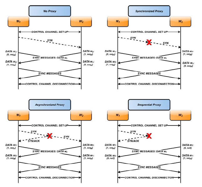
Proxy categories: To classify a transparent web proxy we can take advantage of the fact that its retransmission behaviour can fall into three categories. As represented in Fig. 7, a transparent proxy can either be:
Synchronous, when it only processes and forwards the packets which are received with a FIFO approach.Asynchronous, when it immediately responds to the SYN packet sent by the client with a SYN-ACK and forwards the SYN packet to the server simultaneously without waiting for an ACK.Sequential, when it does not initialise any TCP session with the server before it receives a PSH-ACK packet from the client.
Test case: To verify if there is a web transparent proxy in the communication path, and its category, we define the following test case with two worker nodes W1 and W2 where they respectively play the role of the client and the server:
W1 and W2 create a control channel between each other.W1 sends a SYN packet on port 80 to W2 while we prevent W2 from sending the SYN-ACK reply.W1 (or W2) listens for incoming SYN-ACK (or SYN) packets.W1 and W2 send sync messages to each other to ascertain whether the other party received the expected SYN or SYN-ACK packet. These messages also embed the initial sequence number of the connection (set to NULL if W2 did not receive the initial SYN).W1 and W2 notify each other with sync messages that they are ready to disconnect from the control channel.W1 and W2 terminate the control channel connection.
Fig. 8 illustrates how the exchanges of packets on the data and control channels work. After it receives the information from the remote node, a worker can reason about the presence and category of a transparent proxy. For instance, if W2 did not receive any SYN before a certain time, the test is over since we know that there is a sequential proxy3. If it received it, we check whether W1 received a SYN-ACK packet. If so, we conclude the presence of an asynchronous proxy. Finally, if no SYN-ACK packet has been received by W1, we compare the sequence numbers of the initial SYN packet for the TCP connection. If they are different, there is a synchronous proxy between the two nodes. Otherwise, we conclude that there is no proxy.
Main finite state machine: The main state machine for the aforementioned test case is represented in Fig. 9. Again, it is simple to understand as all the low-level primitives are hidden inside the nested state machines. It also shows how we can take advantage of the nesting feature to use nested state machines from other use cases. For instance, this test case uses three states already defined and presented in subsection 4.1.
In addition to these states, we present four new states dedicated to inferring the presence and category of a transparent web proxy:
VARIABLES_SET_UP: builds the SYN packet and provides the name of the data channel queue on which the packets will be stored.
SYN_HANDLER:W1 sends the SYN packet, both W1 and W2 wait for a packet on their data channel queue.
REMOTE_RECEIVED_GETTER: sends to the other worker whether it received the expected TCP packet and the initial SYN sequence number.
RESULT_SETTER: gives a conclusion based on the packets received and the SYN sequence numbers.
As we already described three of the state machines in subsection 4.1, and since they are the same in this use case, we only present the new states in more detail.
Figure 8. Representation of the four possible scenarios, depending on the presence and category of a TCP proxy between w1 and W2.
MAIN: The logic of this state machine is similar to the main state machine in the DNS redirection use case. We sequentially go from one state to another. The complexity is hidden in the nested state machines that we execute using the CALL primitive. The previous use case was totally symmetric, since the two nodes were sending the same request R to a DNS server. Here, the symmetry is broken as the two nodes act either as the client or the server. Nevertheless, we try to reduce the asymmetry of this test to only one variable, referred to as the role. The role does not appear on the main state machine, so as to maintain a clean symmetry at the highest level. The nested state machines can retrieve the role that the master assigned with the help of the GET_FILE_ PARAMETER primitive. This primitive can parse and retrieve the value of a specific variable from a configuration file transmitted by the master to launch a test campaign.
VARIABLES_SET_UP: This state is similar to the one with the same name in subsection 4.1. If the state machine has the role of the client, it creates a TCP SYN packet with the destination IP set as the server’s IP address. The destination port is set to 80 for the HTTP protocol. The source port and the sequence number are random. Independently of the role of the state machine, we define the name of the data channel queue to indicate at which place the received packets are stored. We also assign a filter to this queue so that it only listens for the TCP replies based on the source port. When this operation is done, the state machine starts to listen for incoming packets and stores the ones that are not filtered out. It forwards the name of the queue to the next state machine so that it can use it to process received packets.
SYN_HANDLER: This state sends a SYN packet from W1 to W2 and processes the first packet recorded using the name of the queue given as input parameter. If the node that executes the program is the client, it sends the SYN packet to the remote worker with the SEND primitive and stores its sequence number into a sequence variable. This operation is only necessary for the client as the server does not need to send any packet. Both the client and the server then start to process the packets received on the data channel queue. The program triggers a PACKET_AVAILABLE event as soon as a packet is available in the queue. They declare a new variable received and store a 1 into it to indicate that they received a reply. Since we want to compare the initial sequence number of the TCP session for both nodes, we also extract and store the sequence number of the SYN packet into the sequence variable for the server. Conversely, if the node does no t receive any packet, a TIMEOUT event is raised and we store a 0 into the received variable to indicate that the local state machine did not receive any reply. If it is the case of the server, the sequence variable holds the value NULL. The nested state machine returns the received and sequence variables to the main state machine that then forwards them to the next state.
REMOTE_RECEIVED_GETTER:This state is responsible for the exchange of data between the two worker nodes. It calls a nested state machine that sends one sync message to first synchronise with the remote worker. Inside this message, it stores the received and sequence local variables. The state machine then waits for the remote variables contained within a sync message in the control channel queue, using the WAIT_SYNC_SIGNAL primitive. As soon as a sync message is available on the queue, the state machine triggers a SYNC_AVAILABLE event to resume program execution. The nested state machine extracts the variables stored in the sync message and returns them to the main state machine. As a result the program now knows everything about what happened locally and remotely when the client sent a SYN packet.
RESULT_SETTER: The final step of the pipeline before disconnecting the control channel. The two machines use the local and remote values, along with their respective role in the scenario to infer the presence of a proxy and its category. The nested state machine called for this task only relies on the guard mechanism within the transitions to provide the final result. If the server node set its local received variable as 0, then the state machine concludes that there is a sequential proxy. Otherwise, it checks if the client node set its local received variable as 1. In that case, the program infers that an asynchronous proxy is between the two nodes. Finally, if the local and remote received variables are different, we have a synchronous proxy; when they are equal the program says that no proxy is detected. This represents the final result that we can combine with other test cases afterwards to create a more fine-grained test campaign.
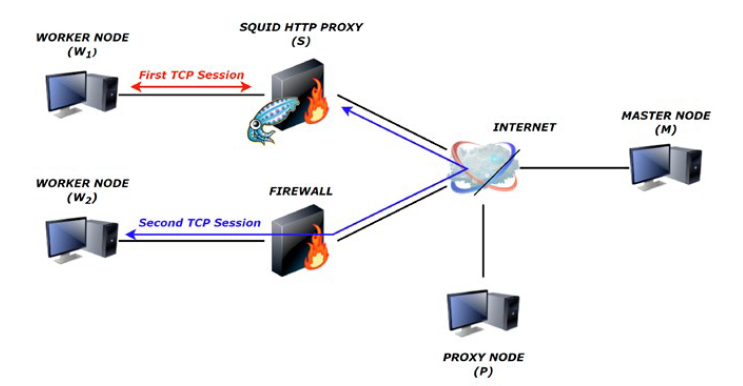
Squid: In order to show how we can apply such a use case, we use our solution to find to which category a Squid transparent proxy belongs to. Fig. 10 represents the architecture for this concrete example. W1 takes the role of the client that wants to categorize S, the Squid transparent proxy that acts as a man-in-the-middle between W1 and the Internet. W2, on the other hand, takes the role of the server. M is the master node that assigns the test case presented across this use case and P is the proxy used to initialise the control channel between W1 and W2. The firewall redirects TCP packets on port 80 to W2 and blocks all other incoming traffic. The test case for this example determines that a sequential proxy is present. To verify that this result is correct, we use Wireshark to analyse the packets sent between the twoTCP connections. The observations validate the conclusion given by our solution. Indeed, we do not observe any packet between S and W2. On the other hand, we can observe many SYN-ACK retransmissions that go to W1 with the IP address of W2, but which are in fact generated by S rather than W2. This phenomenon is due to the fact that W1 does not acknowledge these SYN-ACK packets.
This example illustrates how we could use the state machine to classify a Squid transparent web proxy. We are in the process of reproducing this experiment on many different proxies with a test campaign specifically implemented for this purpose. For the sake of brevity, we defer the presentation of the results for some further workfuture study.
By means of these two use cases, we have demonstrated how we addressed the following specifications, as presented in subsection 3.2:
Ease of useEase of deploymentModularityScalabilityFlexibility
In these test cases, we have ensured ease of use, since an end user does not require any knowledge concerning how DNS and TCP packets work. The user only had to contact the master node M with the name of the test they wished to perform. The architectures we presented are easy to deploy and distribute, as we only need the master node to add and remove nodes (proxies or workers) and be aware of their status. For instance, we described how these use cases work with two worker nodes and a proxy P. They did not need any interaction with M after being assigned the test to run. The use cases highlight how our solution is modular and scalable. We only need the primitives present within our implementation to run a large variety of tests. Furthermore, we leveraged nested state machines to reuse two entire state machines. Finally, we showed how we ensure flexibility as – in the case of the TCP proxy scenario – the data channel is between the two worker nodes. This is not the case when we want to verify whether a semi-active component redirects our DNS requests.
5. Conclusion and future research
In this work, we have presented the foundation of a collaborative platform whose focus is to perform discovery and conformance verification of semi-active elements in network communications. In the future, we wish to make this platform open to anyone, available all over the world and with a large range of protocols supported. For this purpose, we are currently in the process of creating new scenarios, including (but not limited to) WAF discovery, firewall conformance verification, man-inthe- middle attack detection, fuzzing or HTTP smuggling execution, etc. Thus, we hope to have aroused the interest of the readers and welcome the contributions of anyone willing to lend us a hand. We particularly seek for collaborations in the development of the new modules that would make our framework more powerful, and also in the deployment of our platform around the world. The end goal we have in mind is to provide a worldwide map of the semi-active elements that may interfere with our daily communications.
Funding
This work was supported by King Abdullah University of Science and Technology (KAUST): Thuwal, Saudi Arabia.
1This is a major difference with the architecture proposed in [24], in which all communications had to go through some central component. This represents a bottleneck when many workers are running tests at the same time.
2This is a simplified view of the world. We are well aware of the possibility, in some cases, to obtain distinct responses from a given server D for the same request R issued by distinct clients. The identification of the reasons for this to happen could, in fact, be an interesting use case for our platform but such a discussion lies outside the scope of this paper.
3To simplify, we take for granted that the establishment of an HTTP connection between W1 and W2 (through a transparent proxy) would have been successful.

